DSBOARD-AGX Overview and Connector Definitions v1.0
WHAT YOU WILL LEARN?
1- The basic perspective over DSBOARD-AGX v1.0
2- The definitions of buttons
3- The definitions of each connector
ENVIRONMENT
Hardware: DSBOARD-AGX v1.0
The Basic Perspective over DSBOARD-AGX v1.0
Forecr’s DSBOARD-AGX v1.0 is industrial carrier board based on Nvidia Jetson AGX Orin processor module for edge analytics. It is compatible with multi stream deep learning applications.


TECHNICAL SPECIFICATIONS
NVIDIA Jetson AGX Orin SoM options
1x HDMI 2.0(max resolution 3840x2160)
1x Gigabit Ethernet
2x USB 3.1
1x Camera Connector(Total 16-lane)
1x CAN Bus
2x Digital Inputs
3x Digital Outputs
2x Type-C (software recovery and debug)
1x M.2 Type-M Key PCIe Gen4 x4 (For High Speed Storage)
1x M.2 Key-B
1x microSD
1x Fan Connector
1x 2-Pin Header for RTC Battery
1x Serial Communication Connector(1x UART, 1x I2C, 1x SPI)
High Speed Expansion Connector(1xMGBE, 1x PCIe x4, 1xI2S, 1x I2C)
18-32 VDC Input
Ambient Conditions: -40°C … +85°C
OS: Ubuntu Linux 20.04
Dimensions: 100 mm x 100 mm
The Definitions of Buttons
DSBOARD-AGX Recovery Pushbutton
The DSBOARD-AGX implements a recovery pushbutton. Recovery button should be pressed with reset button at the same time. After released reset button, recovery button should be pressed a little bit more (min. 250 ms). It is located on the front side of the board.
DSBOARD-AGX Reset Pushbutton
The DSBOARD-AGX implements a reset button. It is recommended to use needle-like material. It is located on the front side of the board.
The Definition of Each Connector
DSBOARD-AGX Power Connector
The DSBOARD-AGX implements 4-Pin Power Terminal Connector that accepts +18V to +32V DC power. The mating connector is "1708595". The first and the third pins are positive , second and fourth pins are negative. The power connector is located on the rear side of the board.

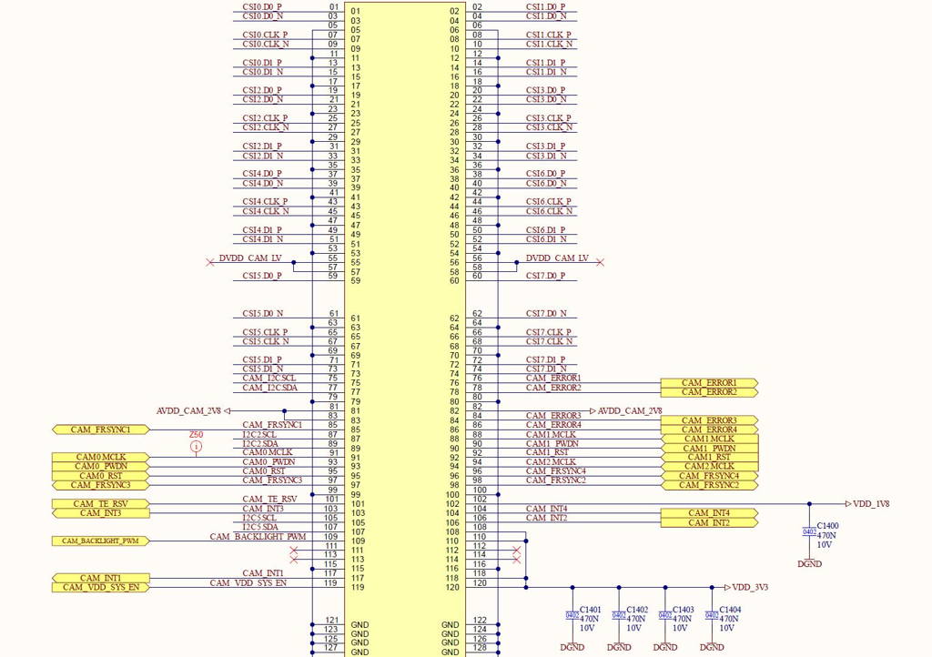
DSBOARD-AGX Camera Connector
The DSBOARD-AGX implements 16-lane CSI camera connector for camera adapter boards. The connector model is QSH-060-01-H-D-A-K-TR. It is located on the bottom side of the board.
DSBOARD-AGX 2-Pin Header for RTC Battery
The DSBOARD-AGX implements 2-Pin header for RTC Battery. The input voltage for RTC have a range of 1.85V to 5.5V. The mating connector is 0014562021 produced by Molex. It is located on the bottom side of the board.
DSBOARD-AGX SD Card Connector
The DSBOARD-AGX implements a micro SD Card connector and nano SIM card connector together. The bottom part is used for micro SD card and the upper part is used for nano SIM card connector. It is located on the front side of the board.
DSBOARD-AGX M.2 Key-M Connector
The DSBOARD-AGX implements a M.2 M-Key Connector for suitable modules. The M.2 M-Key Connector is located on the bottom side of the board.
DSBOARD-AGX M.2 Key-B Connector
The DSBOARD-AGX implements a M.2 B-Key Connector for suitable modules. This connector is located on the bottom side of the board.
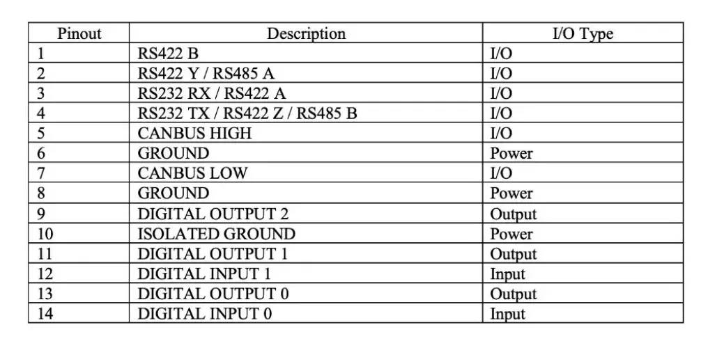
DSBOARD-AGX I/O Terminal Connector
The DSBOARD-AGX implements 14 pins GPIO Expansion connector which has 3 digital output pins, 2 digital input pins, RS232-RS422-RS485 & CANBus pins. The mating connector is “1790344” (DFMC 1,5/ 7-STF-3,5) produced by Phoenix Contact.

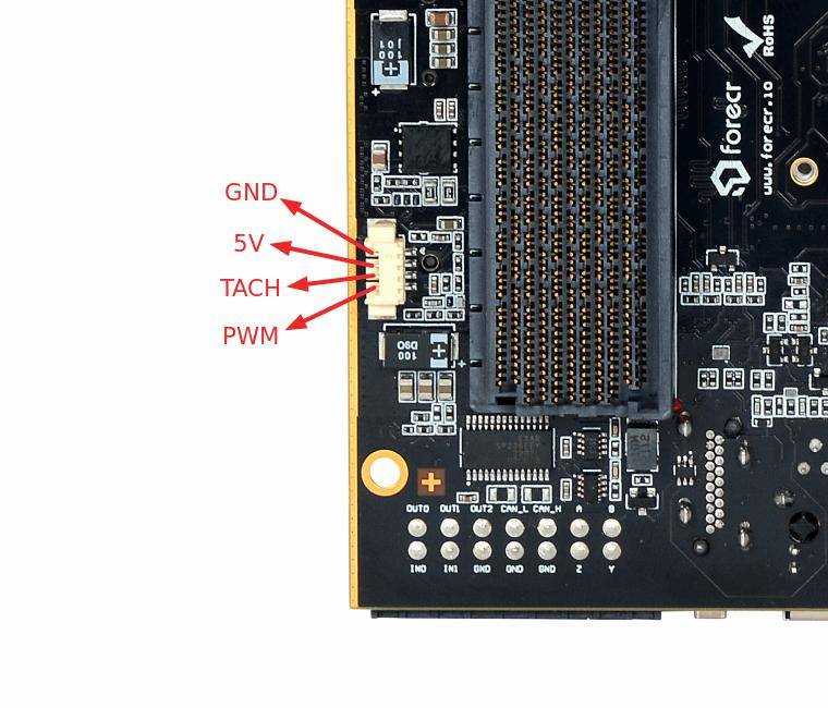
DSBOARD-AGX Fan Connector
The DSBOARD-AGX implements 4 pins header for fan connector (same pinout as NVIDIA's Jetson developer kits' fan connector). It is located on the front side of the board. It mates with 0510210400 from Molex Picoblade series.
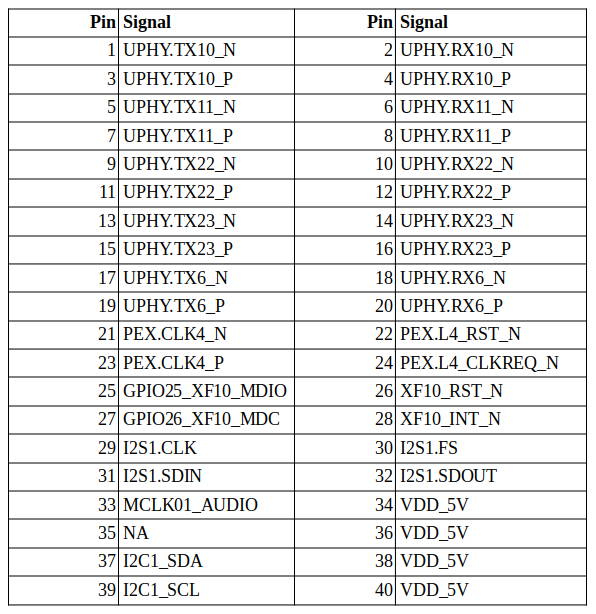
DSBOARD-AGX High Speed Expansion Connector
The DSBOARD-AGX implements 40 pins GPIO Expansion connector which has 1x PCIe x4, 1x MGBE, 1x I2S, 1x I2C. The Connector model is QSH-020-01-L-D-DP-A from Samtec. The mating connector is QTH-020-01-L-D-DP-A-K. The connector is located on the bottom side of the board. As a note; I2C, I2S signals are at 1.8V level.

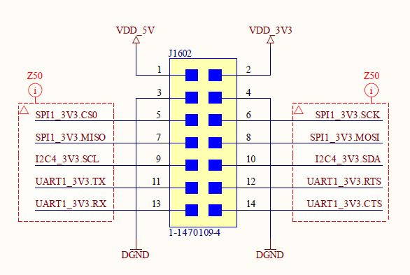
DSBOARD-AGX Serial Communication Connector
The DSBOARD-AGX implements 14 pins GPIO Expansion connector which has 1x SPI, 1x UART, 1x I2C. The Connector model is 1-1470109-4 from TE Connectivity. The mating connector is 1-111626-8. The connector is located on the bottom side of the board.
DSBOARD-AGX HDMI Connector
The NVIDIA® Jetson AGX Orin module will output video via the DSBOARD-AGX vertical HDMI connector that is HDMI 2.0 capable. It is located on the rear side of the board.
DSBOARD-AGX USB 3.1 Type-A Connector
The DSBOARD-AGX incorporates 2 USB 3.1 Type-A connectors with a 2A current limit per connector. The USB connector is located on the rear side of the board.
DSBOARD-AGX 10/100/1000 Ethernet Connector
The DSBOARD-AGX implements RJ-45 ethernet connector for internet communication. RJ-45 connector is connected directly to the NVIDIA Jetson module. The ethernet connector is located on the rear side of the board.
DSBOARD-AGX Recovery Mode Type-C USB Connector
The DSBOARD-AGX implements a Type-C USB connector to allow to install or upgrade the operating system. It is located on the bottom side of the board.
Attention: The recovery USB connection has been designed on the USB type-A connector (bottom port (near to the PCB)) for rev-1.0 carrier board. The newer revisions has this interface on the USB type-C port as expected.
DSBOARD-AGX Debug Mode Type-C USB Connector
The DSBOARD-AGX implements a Type-C USB connector to access the module by using serial connection. It is located on the bottom side of the board.
Thank you for reading our blog post.


