How to Use MCP2515 Module with DSBOARD-NX2?
WHAT YOU WILL LEARN?
1- How to configure BSP files to enable MCP2515 driver?
2- How to connect MCP2515 to GPIO Extension Port?
3- How to communicate MCP2515 via Can Bus?
ENVIRONMENT
Hardware: DSBOARD-NX2 with Jetson Xavier NX
OS: Jetpack 4.6
In this blog post, we will use MCP2515’s Can Bus. First we will configure BSP files and flash the module. Then, we will connect MCP2515 to GPIO Extension port. Afterwards, we can communicate with a Can Bus via MCP2515. In this blog post we communicated with the same board which has a Can Bus on IO connector.
Configuring BSP Files
Open the NVIDIA SDK Manager. Select “JetPack 4.6” for Target Operating System and “Jetson Xavier NX modules” for Target Hardware (The “Host Machine” components are not required). Then continue to Step 2.

Choose only “Jetson OS”, accept the terms & conditions and continue to Step 3.

The SDK Manager will ask the username’s password. Fill it and continue.

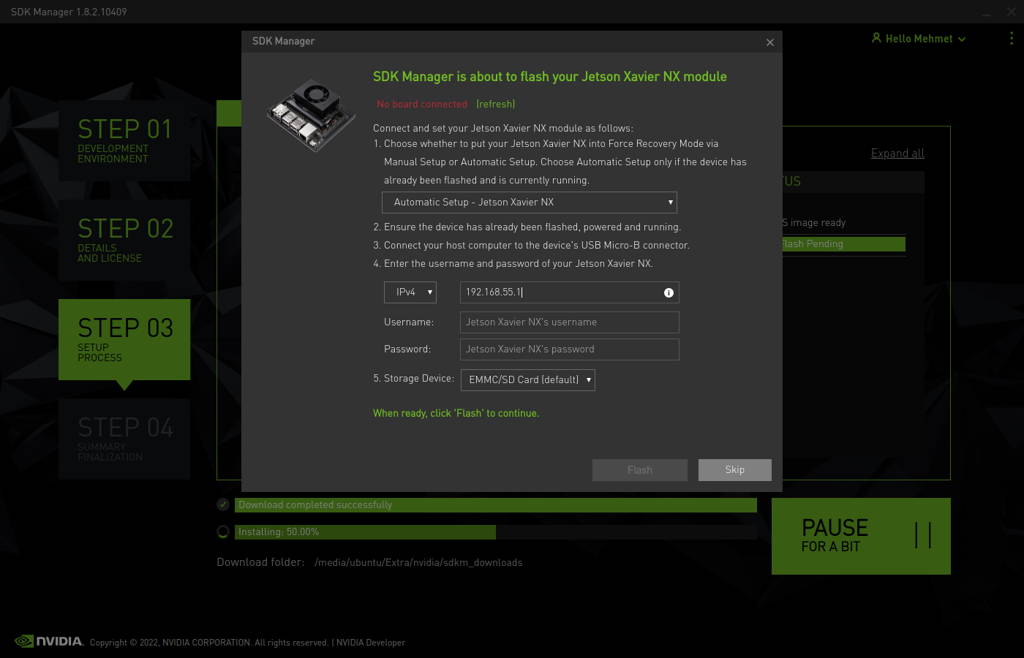
After the Jetson OS has created, the SDK Manager asks the Jetson module’s flashing style. Just skip it and exit from the SDK Manager.

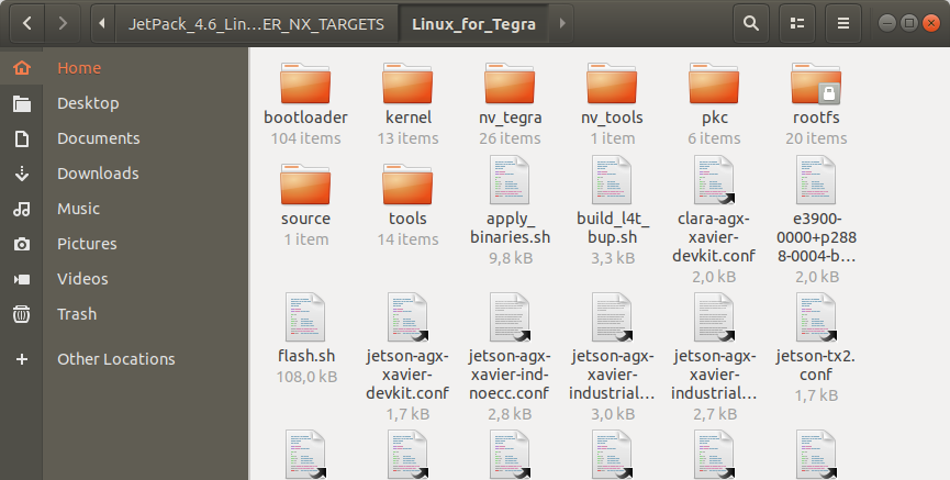
Open the target HW image folder. (${HOME}/nvidia/nvidia_sdk/JetPack_4.6_Linux_JETSON_XAVIER_NX_TARGETS/Linux_for_Tegra/)
Download MCP2515 BSP files from here & extract it.
Copy files that mentioned below to the directories inside JetPack-4.6.
Move Image file inside to ./kernel directory and overwrite on the Image file that exist before.

Move tegra194-p3668-all-p3509-0000.dtb file inside to ./kernel/dtb directory and overwrite on the file that exist before.

Move tegra19x-mb1-pinmux-p3668-a01.cfg file inside to ./bootloader/t186ref/BCT directory and overwrite on the file that exist before.

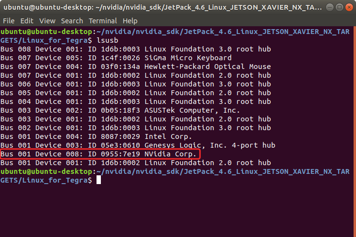
Return to the “Linux_for_Tegra” folder and open a Terminal.

Type "lsusb" and check the device connected in Recovery mode (0955:7e19 NVidia Corp.)
After this step, you can flash the module with the command below.
sudo ./flash.sh jetson-xavier-nx-devkit-emmc mmcblk0p1

When the flash is successfully done, the module will reboot and open itself.
Connecting MCP2515 to GPIO Extension Port
Connect MCP2515’s SPI pins to Extension Port’s SPI pins (SPI0). And connect MCP2515’s INT pin to UART0 CTS pin. (We configured UART0 CTS pin as an Output at pinmux configuration.)
You can see below where the connector mounted on the board and connector’s pin schematic.

Note: The little arrow above the connector represents the first pin.
Note2: You must connect a 120 Ohm termination resistor between L and H pins.
Note3: You must connect L pin to CAN_L and H pin to CAN_H.

Communication via Can Bus
Now, execute mcp2515_test.sh file and test your Can Bus. Before this step, check all wiring are correct.
The MCP2515’s Can Bus will name itself as “can0” and module’s internal Can port will be named as “can1”.

If you have communication issues, you can check MCP2515 driver with typing these commands:
dmesg | grep mcp
dmesg | grep can1
